
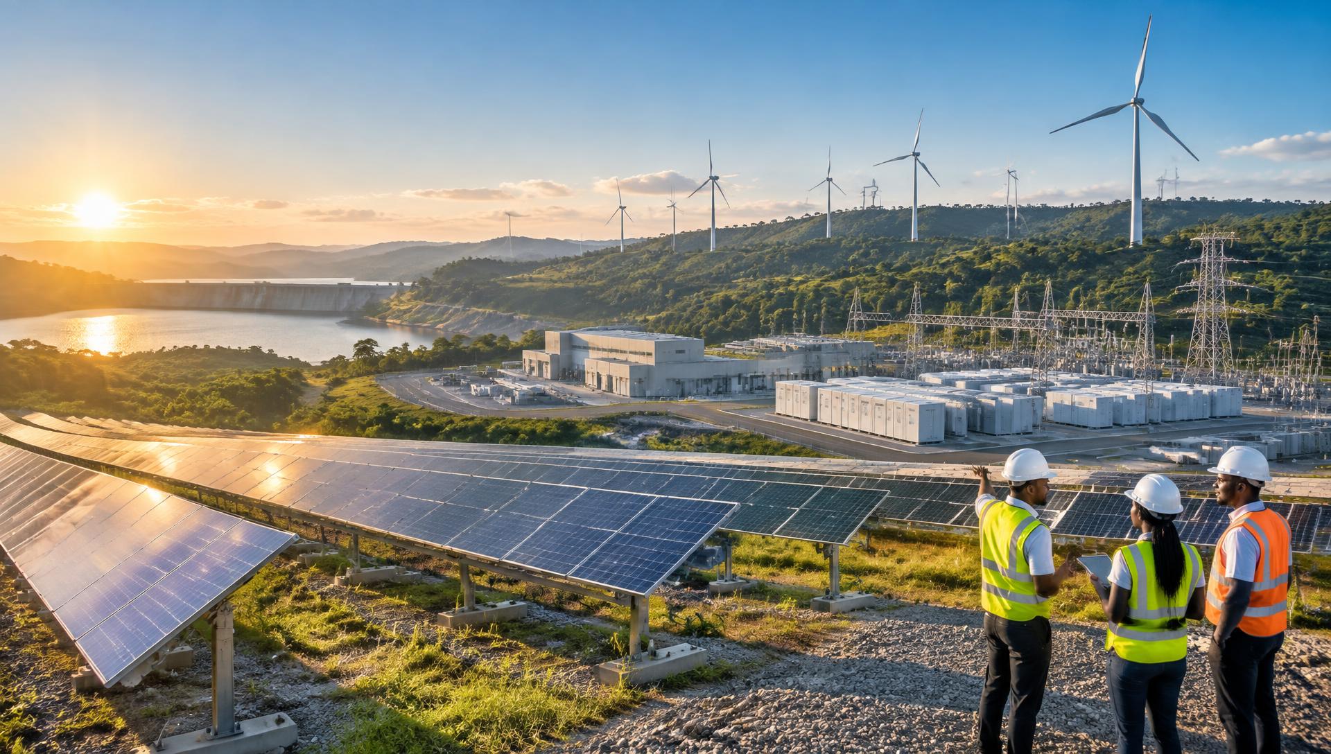
Solar-Wind-Hydro Hybrid Mega-Complex
A captive 500 MW tri-source generation backbone immune to grid instability. Zero marginal cost, 24/7 — the reason Ghana's Eastern Corridor is a structural advantage rather than simply a location.
Four sources. One firm supply.
Solar PV
300 MW peak- Technology
- Bifacial mono-PERC, single-axis tracking
- Irradiance
- 5.5 kWh/m²/day equatorial belt
- Role
- Primary daytime generation
- Land footprint
- Approx. 60% of generation area
Eastern Corridor Wind
150 MW- Technology
- Utility-scale onshore turbines
- Regime
- Predictable evening/night profile
- Role
- Complementary to the solar curve
- Integration
- Shared 33 kV collector network
Hydro balancing
50 MW- Technology
- Contracted hydro dispatch
- Role
- Dispatchable firming and black-start
- Response
- Sub-minute ramping
- Function
- Residual load and outage cover
ASIS AI dispatch
99.7% uptime- Function
- Second-by-second co-optimisation
- Inputs
- SCADA · EMS · weather · load forecast
- Objective
- Lowest-cost firm supply to H₂/DRI/MOE
- Storage
- BESS buffering for ramp events
How the complex is organised on the 500-acre parcel.
Tracker arrays laid out on the western plateau of the 500-acre parcel, arranged in blocks around internal service roads.
Turbine string on the exposed northern ridge line, sited for prevailing corridor wind and set back from process areas.
Substation, battery storage, hydro interconnection bay and the central control room housing ASIS.
Electrolysers and hydrogen storage placed adjacent to the energy park to minimise electrical distance.
DRI-EAF and MOE units, with the circular-economy and CCUS loop closing back into the energy park.
Rail/road corridor and laydown yards running to the harbour route for feedstock in and product out.
Zoning places generation upwind and upslope of the process islands, keeps electrical distance between generation, electrolysis and melting as short as possible, and reserves the logistics spine for harbour-bound movements.
From enabling works to full tri-source dispatch.
- Phase 0 · 2026
Enabling works & studies
- Grid-independence and resource studies finalised
- Geotechnical, environmental and social surveys
- Generation EPC packages tendered
- Internal roads, water and site security
- Phase 1 · 2027
First solar blocks energised
- Substation and 33 kV collector network built
- Initial tracker blocks commissioned
- Battery storage first tranche installed
- ASIS dispatch commissioning in shadow mode
- Phase 2 · 2027–28
Wind & hydro integration
- Turbine erection on the northern ridge
- Hydro interconnection bay energised
- Tri-source control logic live
- Electrolyser power supply handover
- Phase 3 · Q4 2028
Full 500 MW tri-source dispatch
- Complete generation fleet at rated output
- Firm 24/7 supply to hydrogen and steel islands
- ASIS autonomous dispatch at 99.7% uptime
- Synchronised with first green steel pour